This article is part of my series of projects around Ternary Computing and Processor Design. Click here to see the list of projects of this series.
Last time, we looked at the basics of ternary logic. Now let's implement a more complex circuit : an Arithmetic Logic Unit. This component adds two ternary words and outputs the sum. In addition, we want to be able to do subtractions. Here, to keep diagrams reasonable, I will describe a 3-trit (one tribble) ALU.
The main operation of the ALU is the addition. This operation, as in any numerical base requires a carry system, a way to propagate the carry from the addition from one digit to the next. I will use a ripple-carry system and not a carry-lookahead. That means adding the two trits of one digit of the words requires the carry of the previous pair of digits, therefore we have to wait for the previous sum to be completed. Consequently, as the word length increases, so does the time required for the operation to complete in a linear way. In a full processor, this reduces the maximum frequency, or requires complex timing and scheduling.
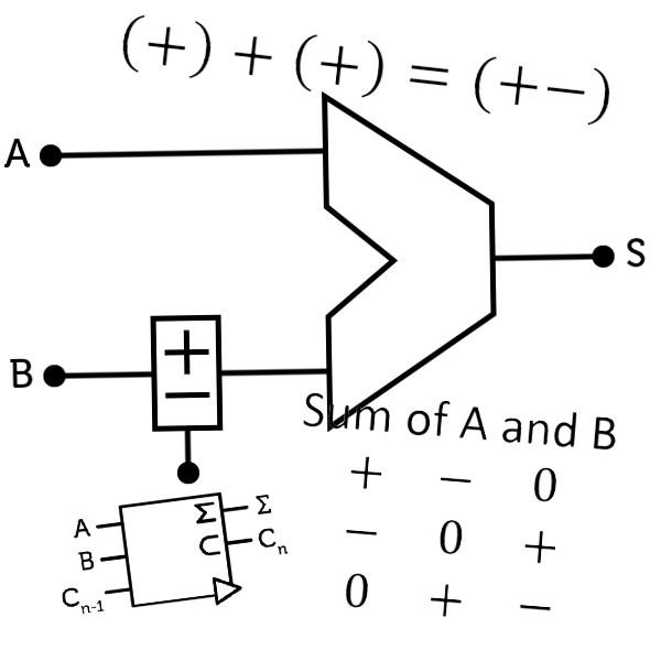
As with binary, we start by creating a half-adder, which add two trits and outputs the sum as well as the carry of this operation. For instance, $$1 + 1 = 2$$ in ternary is $$(+) + (+) = (+$$$$-)$$, meaning the sum of $$+$$ and $$+$$ is $$-$$ and the carry is $$+$$. In truth table :
Sum of A and B :
$$
\begin{bmatrix}
+ & - & 0 \\
- & 0 & +\\
0 & + & -
\end{bmatrix}
$$,
carry of A and B :
$$
\begin{bmatrix}
- & 0 & 0 \\
0 & 0 & 0\\
0 & 0 & +
\end{bmatrix}
$$.
We recognize the sum of A and B to be the SUM gate (obviously) and the carry is the CONS.
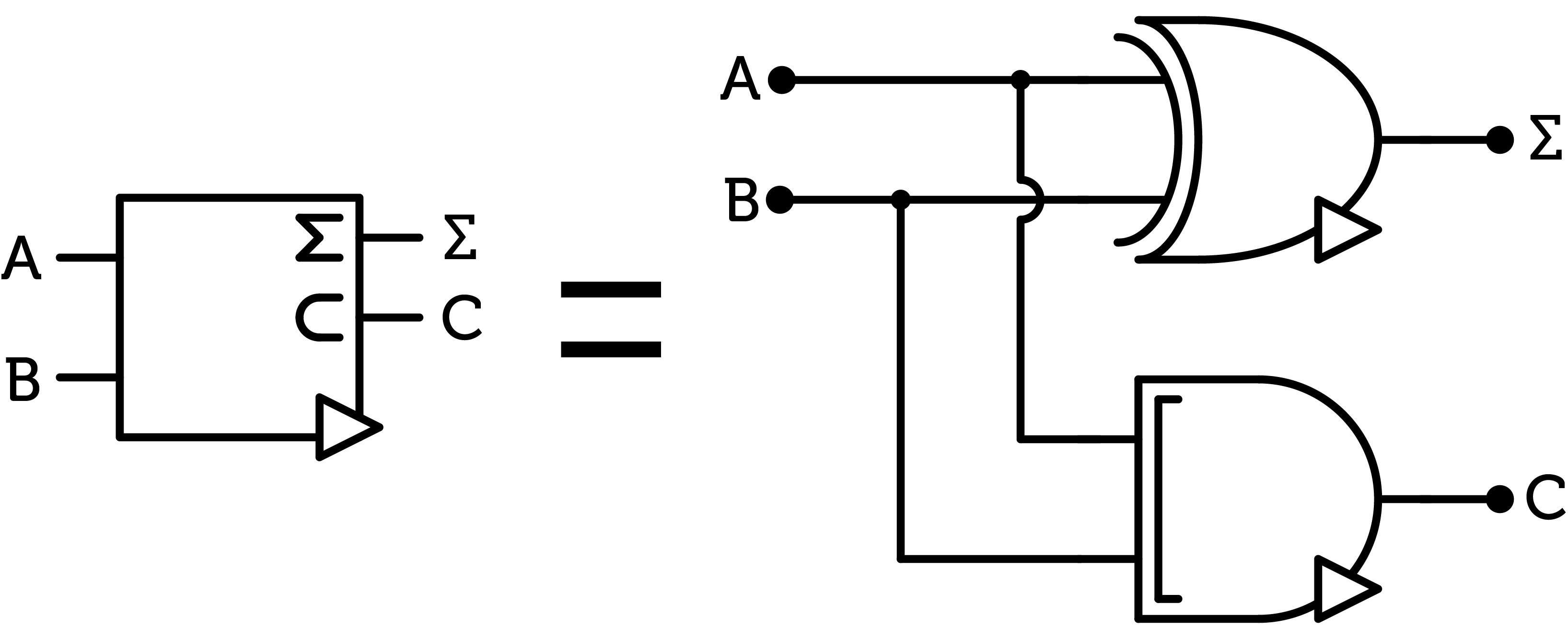
Half-adder
When building the half-adder with transistors, we can actually spare the CONS gate by using the one inside the SUM gate (see the previous post).
Then we combine two half-adders to create a full-adder to add two trits as well as the previous carry. We also have to combine the carries of the two additions with a ANY gate.
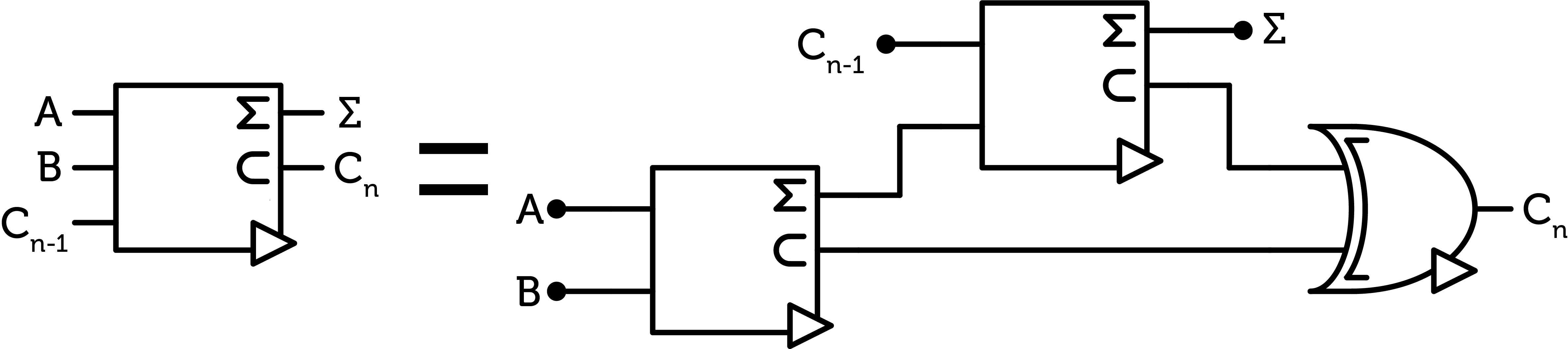
Full-adder
This is the heart of the ALU. The first and last additions of the chain of digits are special as they respectively don’t have a previous carry and don’t have to output a carry. Therefore, the first digit only requires one half-adder, and the last one requires two SUM gates. For a n-trit word :
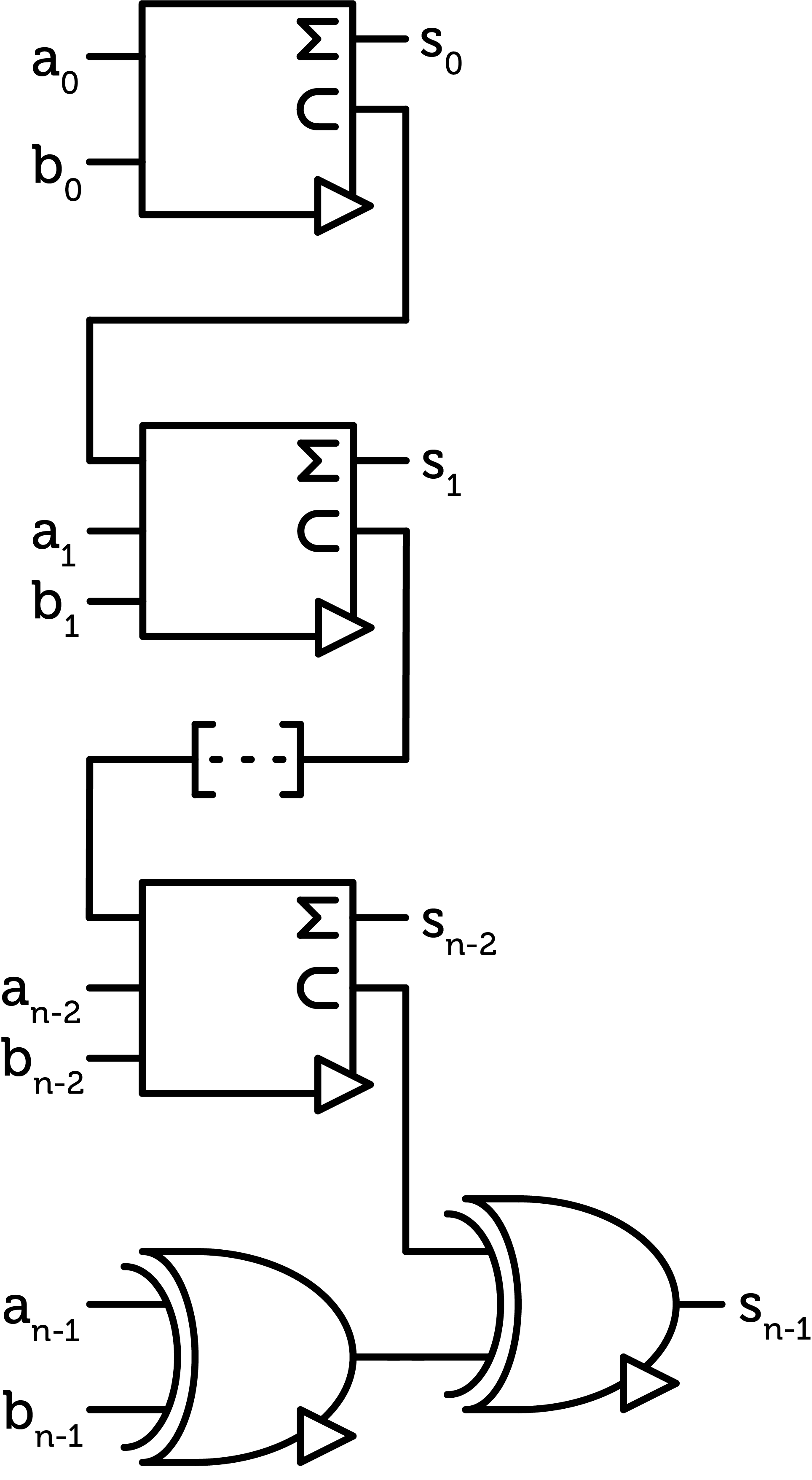
Adder chain
We can actually save many transistors by negating most of the outputs.
Then to subtract B from A, we can just invert B before the addition. For this, we can create a sign controller with MUL gates :
- $$neg=-1 \quad \Rightarrow \quad Q=-B$$
- $$neg=0 \quad \Rightarrow \quad Q=0$$
- $$neg=+1 \quad \Rightarrow \quad Q=+B$$
For a 3-trit word :
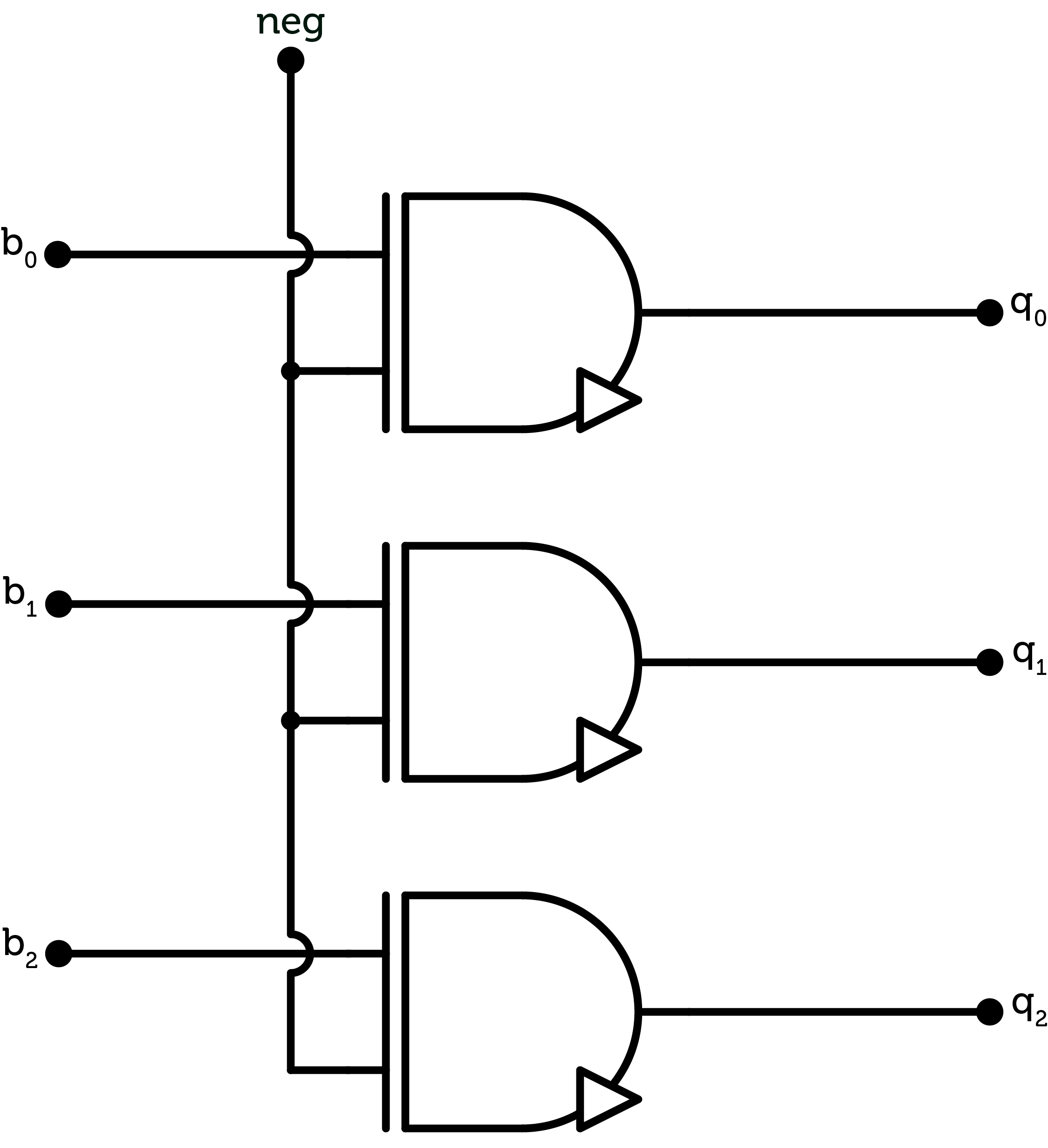
Signal controler
There might be a way to bring the cost of each NMUL gate by factoring some of the transistors between one NAND and the OR gate and thus spare one CMOS pair per gate. Another factorization might be possible between the NMUL gate inside the signal controller circuit further reducing the cost. This will be explored in the future. Anyway, factorizing CMOS pairs between gates won’t be practical for the many-boards modular design approach I described earlier and the savings might not be worth it. Therefore, it would be more useful for a single board design.
Finally, here is the ALU with the $$neg$$ signal to control B and do subtractions. In a full processor, this signal will be controlled by the instruction decoder.
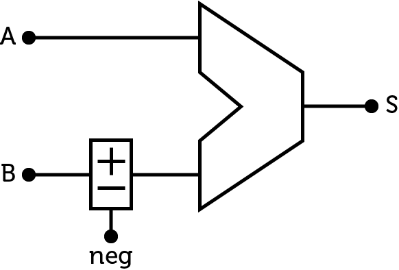
ALU with subtraction
NOTE : Some ALU also include a flag signal for the overflow (when the operation results in a number outside the range of the architecture). It can be achieved by replacing the circuitry of the last digit with a usual full-adder. This of course increases the cost.
This article is part of my series of projects around Ternary Computing and Processor Design. Click here to see the list of projects of this series.
Go back to the list of projects