This article is part of my series of projects around Ternary Computing and Processor Design. Click here to see the list of projects of this series.
In this project, I implemented an incrementally more advanced architecture than the SAP1 I described in a previous article. Again, I used my TernaryVerilog language and tools, which I kept improving during this project.
Motivation
The SAP1 architecture uses a central common data bus which is used for pretty much all data transfers and functions of the processor. Consequently, we can only utilize one component at a time, while the rest of the processor waits and does nothing, thus wasting potential performance.
Instruction pipelining attempts to keep every component of the processor busy by dividing the execution of each instruction into a series of sequential steps performed by different corresponding circuits making up the stages of the pipeline. That way, while one instruction is being processed in one stage of the pipeline, the next instruction can be processed at another.
The analogy often used to visualize pipelining is that of washing and drying clothes. Without pipelining, we first put the first batch of clothes into the washing machine, wait one hour for it to finish, then put the batch of clothes into the drying machine, wait another hour for it to finish and only then repeating with the second batch. However, with pipelining, while the first batch is being dried, the second is being washed. One batch of clothes still takes two hours to process, but we finish processing one batch every hour instead of every two hours.
In processor architectures, pipelines can be only a few stages deep or many. There is a trade-off between pipeline depth, circuit complexity, flush cost, and other factors I wont be explaining here. In this article, I will use a simple 4-stage pipeline, hence the name Simplified Pipelined processor, or SimP.
SimP processor architecture
Overview
The SimP architecture can perform simple arithmetic operations - additions and subtractions - on signed or unsigned 16-bit values. It also supports unconditional jumps and conditional branching.
Unlike the SAP1, the SimP is a Harvard architecture, meaning the instructions and the data are stored in different memories. The instructions are stored in a 256x16 bits ROM and the data is stored in a 256x16 bits RAM.
The pipeline is four stages deep, using many registers. There are four general-purpose registers grouped in the register file, and two main internal registers A and B to store the operands of the instructions before execution.
Pipelining introduces hazards due to dependencies between instructions. For instance, if an instruction wants to read the value of a register before the previous instruction has updated it with its result, it is called a Read-After-Write hazard (RAW). In this architecture, we avoid hazards by stalling at the decode stage which necessitates keeping track of which registers are waiting to be updated. We also stall until resolution of conditional branches to avoid having to deal with mispredictions and pipeline flushes. Those concepts will be explored in a future architecture.
Additionally, if the decode stage stalls waiting for the result of a previous instruction, it can grab the value from the write-back stage instead of having to wait for the write-back stage to update the register file. This is called forwarding and saves one cycle on RAW dependencies.

SimP architecture
Instruction Set
The SimP ISA uses 4-bit opcodes to encode 16 instructions. It uses a load-store approach, meaning it separates memory access instructions from ALU operation instructions : in order to load a value from memory, perform an operation on it using the ALU, and storing the result in memory, we have to use at least three instructions : first load from memory to a register, then use the register as an operand for the ALU operation and write the result to another register, and finally write the value of this register back to memory.
Additionally, most instructions use a 3-operand design : the first operand is the destination register where the result of the operations will be written, and the other two are the operands of the operation itself. Two bits are used for each operand to reference one of the four general-purpose registers. Furthermore, one operand can be an 8-bit immediate value. This is used either as an immediate value for arithmetic operations, as the memory address for load-store instructions, or as the jump/branch address.
Hence, instructions are encoded as 16-bit words. The first 4 bits are the opcode, and the last 12 bits encode the operands : 2 bits for the destination register, 2 bits for the first operand register and 8 bits for either the second operand register or for an immediate value. Note that conditional branch instructions are a bit hacky as they use the bits intended for the destination and first operand respectively for the first and second operands, as the immediate value stores the jump address.
| Instruction | Syntax | Meaning |
|---|---|---|
| No operation | NOP | do nothing |
| Load from RAM | LOD $1,adr | $1 = dRAM[adr] |
| Load immediate | LODI $1,imm | $1 = imm |
| Store | STR $1,adr | dRAM[adr] = $1 |
| Add | ADD $1,$2,$3 | $1 = $2 + $3 |
| Add immediate | ADDI $1,$2,imm | $1 = $2 + imm |
| Add signed | ADDS $1,$2,$3 | $1 = $2 + $3 (signed) |
| Add immediate signed | ADDIS $1,$2,imm | $1 = $2 + imm (signed) |
| Subtract | SUB $1,$2,$3 | $1 = $2 - $3 |
| Subtract immediate | SUBI $1,$2,imm | $1 = $2 - imm |
| Subtract signed | SUBS $1,$2,$3 | $1 = $2 - $3 (signed) |
| Subtract immediate signed | SUBIS $1,$2,imm | $1 = $2 - imm (signed) |
| Jump | JMP pc | go to pc |
| Branch if equal | BEQ $1,$2,pc | if $1 == $2, go to pc |
| Branch if greater | BG $1,$2,pc | if $1 > $2, go to pc |
| Branch if greater signed | BGI $1,$2,pc | if $1 > $2 (signed), go to pc |
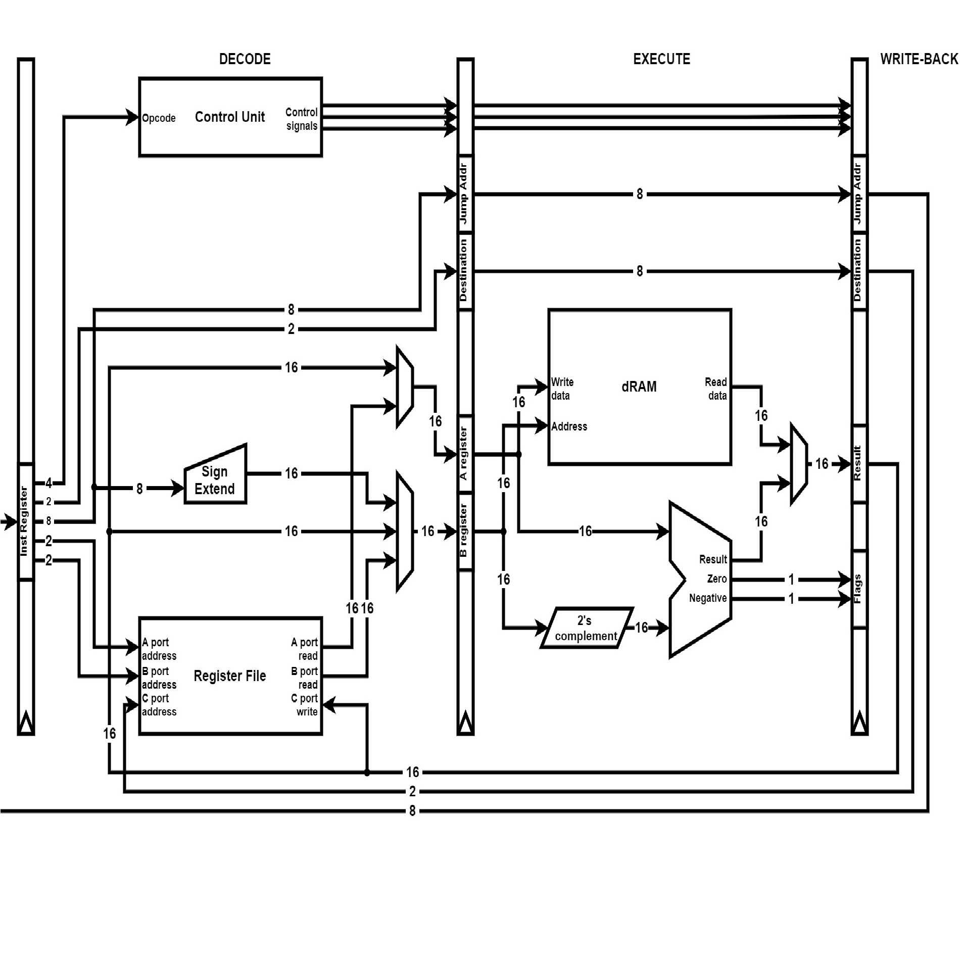
Pipeline
The first stage is Instruction Fetch (IF). The Program Counter is updated (incremented, halted, or written to for jump and branch instructions), then it is used to index the instruction ROM (iROM) for the next instruction which is written to the Instruction Register (IR) on the next rising edge of the clock.
The second stage is instruction Decode (DE). The new instruction is split into the opcode and the operands. From the opcode, the control unit determines the control signals for the decode stage and the later stages. Depending on those control signals, the A and B buses are connected to the correct registers in the register file. The B register can also be connected to the immediate value with sign extension from 8 to 16 bits. Forwarding and hazard prevention are also taken into account. If the instruction writes its result to a register, this destination is extracted from the operands and written to the destination register. If the instruction is an unconditional jump, it is executed at this stage and the Program Counter is updated.
The third stage is execution (EX). The two main operations instructions perform at this stage are arithmetic operations and data RAM access. For the former, the A and B registers are fed to the ALU. For the latter, the A register is used as a Memory Data Register is data is written to RAM, and the B register is used as a Memory Address Register for either memory writes or reads. The result of either operation in fed to the next stage of the pipeline alongside the destination register. If necessary, the ALU flags are updated.
The fourth and final stage is Write-Back (WB). The result on the last stage is written to the Register File, and forwarded to the A or B bus if necessary. If the instruction is a conditional branch, it is resolved at this stage, the Program Counter is updated and the rest of the pipeline can resume.
Benchmarking
Benchmarking is not really relevant as this architecture is so much more capable than the SAP1 yet its ISA doesn't allow for interesting benchmarks. When I finish developing the other architectures on my list, I might create alternative versions with a common more powerful ISA in order to measure the impact of different architectures on performance. This comparison will also require a working circuit optimizer.
In place of benchmarking, here is a video of the SimP architecture running a simple program at 5Hz. This program features some conditional branches and dependencies, therefore the fetch and decode stages have to stall often.
Future work
For the next architectures, I want to explore more complex and modern features. In order, I plan on first implementing better instruction-level parallelism through Tomasulo's scheduling algorithm (SimT). Then, adding speculation, out-of-order execution and branch prediction (SimS). And then caches (SimC).
This article is part of my series of projects around Ternary Computing and Processor Design. Click here to see the list of projects of this series.
Go back to the list of projects