This article is part of my series of projects around Ternary Computing and Processor Design. Click here to see the list of projects of this series.
I'm back working on the Ternary Computer ! If you haven't read the previous articles I made on the topic, go take a look at them. I now started studying at Georgia Tech and I managed to get the project accepted as a Special Problem, basically a small research project. So, articles about Ternary Computing are on their way.
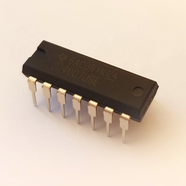
After covering the theory of ternary computing, now for some application. This time, I'm implementing the gates using transistors to build a 3-trit ALU as explained in my Ternary ALU Design article. More specifically, I'm using CMOS pairs from the CD4007. This chip contains three CMOS pairs but only one is usable as they are not independent. This chip comes in a DIP14 package, very useful as we can test it on a breadboard and solder circuits with DIP sockets to change the chip if it breaks down.
The gates I'm going to implement are the five basic gates : NOT, NAND, NOR, NCONS, NANY. NOT actually comes in three versions, the neutral NOT and the positive and negatively biased NNOT and PNOT, but they don't require more circuitry : just one CMOS pair and two resistors to stabilize the output. The other basic gates have two inputs, thus two CMOS pairs plus the two resistors. I initially used resistors on the inputs as well but it's unnecessary.
I also acquired a new dual-rail positive-negative power-supply since the one I had built a few months ago doesn’t work anymore (the capacitors look blown up so I guess I fed it reverse polarity at some point). I use 5V positive and negative but the CD4007 can be driven with up to 15V.
For the two-input gates, the two corresponding transistors of the two CMOS pairs can either be setup in parallel or in series. Two configurations for the NMOS and the PMOS, so four configurations in total for the two pairs. Those are the four basic gates : NAND, NOR, NCONS, NANY.
NOT gates
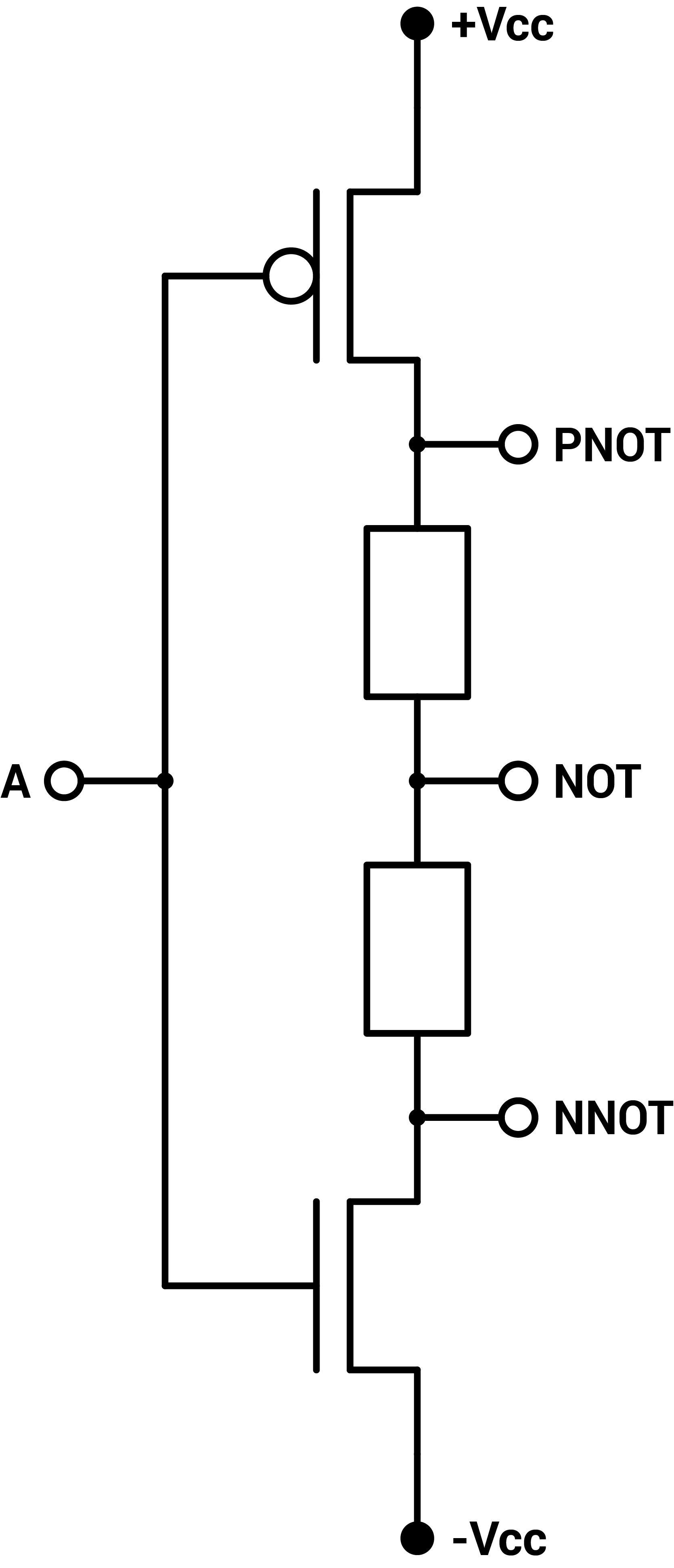
NOT, PNOT and NNOT gates
First the NOT gate. When the input is 0V, both transistors are open and +Vcc and -Vcc cancel each other so that the output is 0V. When the input is +Vcc, the PMOS (top) is closed and the NMOS (bottom) is open and the output is -Vcc. The opposite happens for the input of -Vcc. The PNOT and NNOT biased gates are just the same but the output is above and bellow the resistors respectively. I tested those gates and they worked as expected.
Finally I put two NOT gates back-to-back and we get the original signal back. This means the input of one gate can be driven by the output of another, and not just a direct connection to the power rails or ground. This is critical to build circuits.
NAND gate
The NAND gate (inverted AND) is built with the PMOS in parallel and NMOS in series and we get the matrix $$ \begin{bmatrix} + & 0 & - \\ 0 & 0 & -\\ - & - & - \end{bmatrix} $$

NAND
- If one input is $$ - $$, then the PMOS open the output to the positive rail and the NMOS cuts the output to the negative rail regardless of the other input, and the output is $$+$$.
- If one input is $$0$$ and the other is $$0$$ or $$+$$, then the output is connected to both the positive and negative rails and the output is $$0$$.
- If both inputs are $$+$$, then both PMOS are closed and both NMOS are open so the output is $$ - $$.
NOR gate
The NOR gate (inverted OR) is built with the PMOS in parallel and NMOS in series and we get the matrix $$ \begin{bmatrix} + & + & + \\ + & 0 & 0\\ + & 0 & - \end{bmatrix} $$
NOR
- The gate works like the NAND but in opposite.
NCONS gate
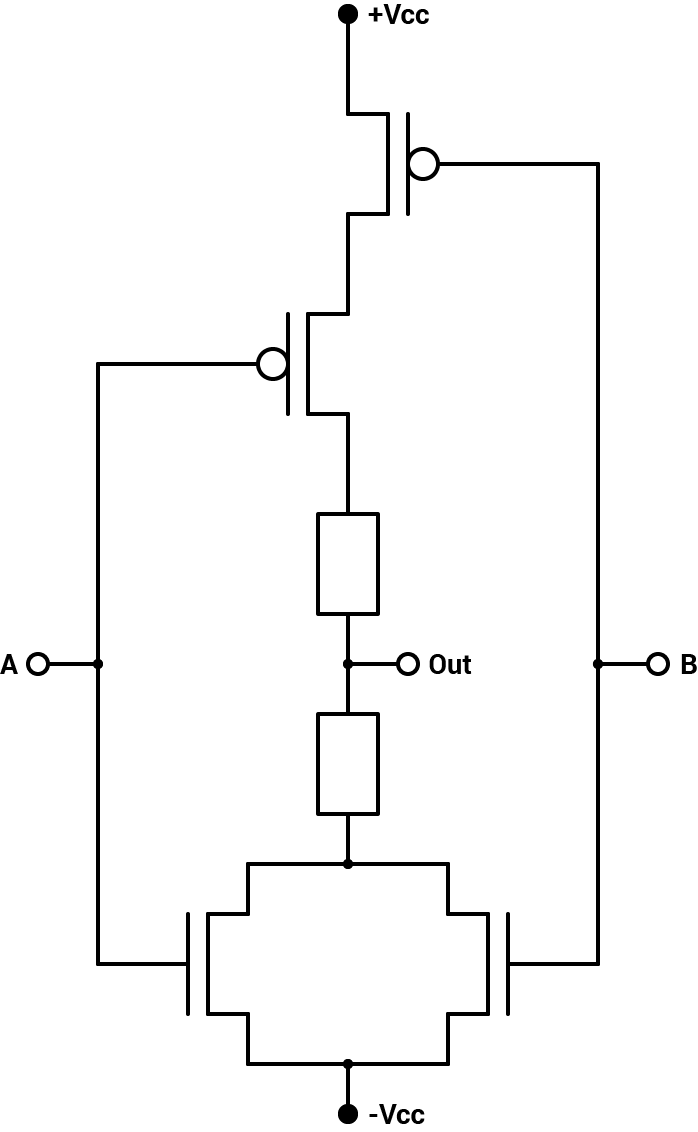
The NCONS gate (inverted CONS) is built with the NMOS and PMOS transistors in parallel and we get the matrix $$ \begin{bmatrix} + & 0 & 0 \\ 0 & 0 & 0\\ 0 & 0 & - \end{bmatrix} $$

NCONS
- If one of the inputs is $$0$$, then both transistors are open and the output is necessarily $$0$$ regardless of the other input.
- If both inputs are $$+$$, then the PMOS transistors are closed and the NMOS are open, setting the output to $$ - $$. Similarly, if both inputs are $$ - $$, then the output is $$+$$.
- If the inputs are $$+$$ and $$ - $$, then on one pair, the PMOS is open and on the other the NMOS is open so the output is connected to both the positive or negative rails and the output is $$0$$.
NANY gate
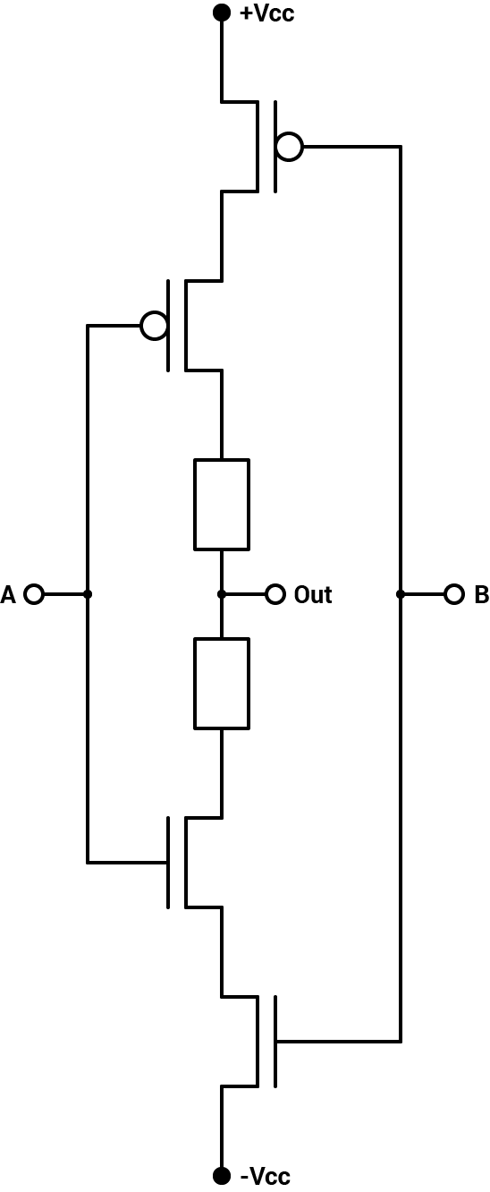
The NANY gate (inverted ANY) is built with the NMOS and PMOS transistors in series and we get the matrix $$ \begin{bmatrix} + & + & 0 \\ + & 0 & -\\ 0 & - & - \end{bmatrix} $$
NANY
- If one of the inputs is $$0$$, then both transistors are open and the circuit works like a NOT gate with the other input.
- If both inputs are $$+$$, then the PMOS transistors are closed and the NMOS are open, setting the output to $$ - $$. Similarly, if both inputs are $$ - $$, then the output is $$+$$.
- If the inputs are $$+$$ and $$ - $$, then on one pair, the PMOS is closed and on the other the NMOS is closed so the output is not connected to either the positive or negative rails and the output is $$0$$.
Electrical properties
While building the gates, I noticed there seems to be a small voltage bias : even when using precise $$+5.00V$$ and $$-5.00V$$, the $$0$$ output was about $$-0.7V$$. I examined that by acquiring a second dual-rail power-supply, fixing the first to $$\pm 5.00V$$ and using the other to measure the output of a NOT gate with an input ranging from $$-5.00V$$ to $$+5.00V$$. The dual-rail power-supply I use can't go below $$1.25V$$ (LM337 and LM317). Here is the result :
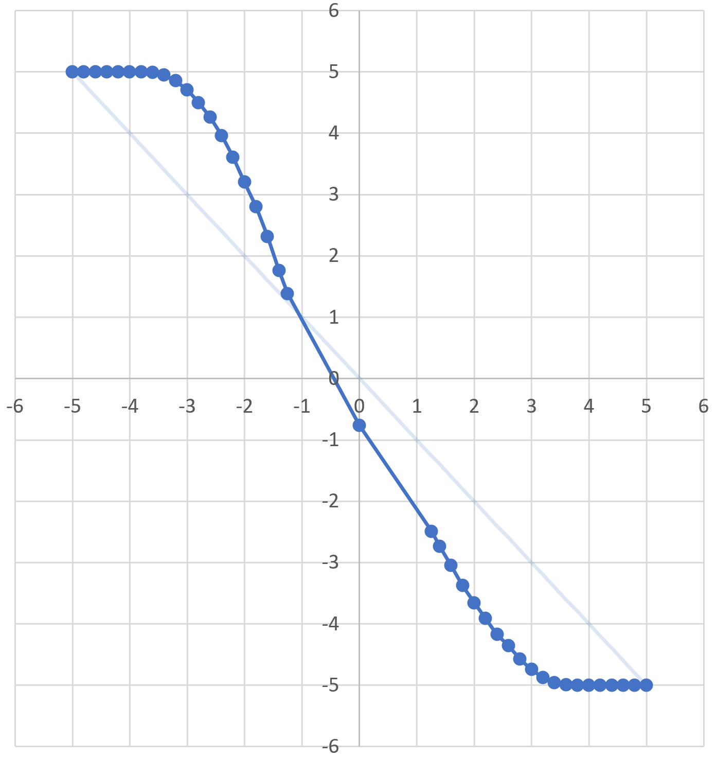
horizontal : input voltage ; vertical : output voltage
As we can see, there is indeed a bias towards negative voltage at small input voltages. This can be an issue as inputting the $$0.7V$$ in an other gate could amplify this small bias (use the $$y=x$$ curve and staircase method). However this was not observed with the NOT gates in series. This has to be kept in mind to diagnose eventual future issues. Adjusting the power-supply to balance this bias might be necessary.
I then wanted to check the propagation time of the CMOS pair of the CD4007. This is how long it takes for the output to be updated after the input changes. The datasheet indicates a propagation time of typically $$35ns$$ at $$5V$$ and $$20ns$$ at $$10V$$. This translates to a maximum frequency of $$28.6MHz$$ and $$50MHz$$ respectively. This is for one CMOS pair. A more complex gate such as MUL or SUM requires multiple such propagation delays, and as I explained in the ALU Design article, a ripple-carry ALU will take many many propagation delays. We can still estimate that for the 3-trit ALU, we can expect in the order of $$100kHz$$, which would be great ! But realistically, there are other factors related to wire length between the gates.
Using the small handheld oscilloscope I had at the time, and a 555 timer clock, I tried to check how fast the NOT gate I built could work. I was quickly limited by the maximum frequency of the oscilloscope and the messy waveform of the 555 circuit I made in a hurry. But the circuit was still working fine at about $$400kHz$$.

blue : clock ; yellow : output of the NOT gate
As all the gates work, I'm ready to finally try to build the processor ! So I ordered over 200 chips, a thousand resistors and other components. Going forward, breadboards are obviously not going to scale. In the next article, I will explain the PCBs I designed and test them.
This article is part of my series of projects around Ternary Computing and Processor Design. Click here to see the list of projects of this series.
Go back to the list of projects