This small project was an assignment for ECE6100 - Advanced Computer Architecture at Georgia Tech. The task was to implement Tomasulo's algorithm, an instruction scheduling algorithm that allows for Out-Of-Order execution and parallelization of operations on multiple functional units. I implemented the algorithm in Python. The simulator is heavily configurable and outputs to a text file a table with each row describing the state of the processor at one cycle.
The algorithm
Overview of the architecture
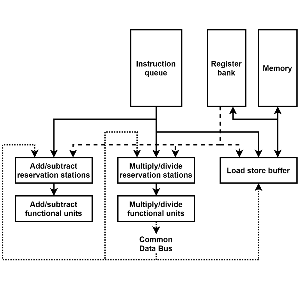
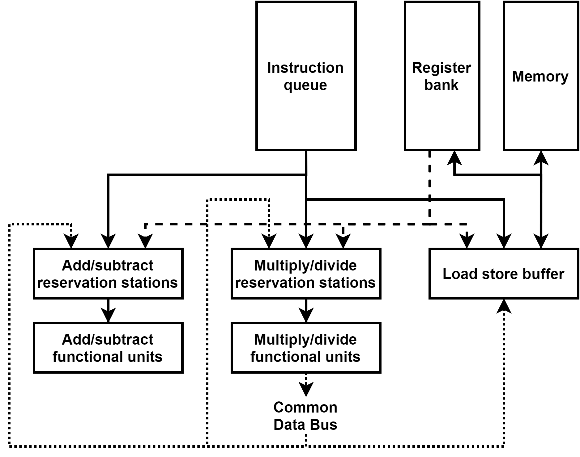
The processor is based on the Tomasulo’s architecture. The instructions are loaded into an instruction queue waiting to be issued to reservation stations. Reservation stations are grouped into three banks, one for add and subtract operations, one for multiply and divide operations, and one for load and store operations. Instructions in reservation stations wait for their operands to be resolved (from the register bank or the common data bus) and for an available functional unit to begin execution. The functional units are either dedicated to add/subtract operations, or multiply/divide operations (with a parameter to differentiate functional units for multiply and divide operations). The load/store reservation stations are arranged in a circular buffer (table with read and write pointers) and the operations in this buffer are handled sequentially in order.
Tomasulo's algorithm
Each entry in the reservation stations for addition, subtraction, multiplication and division operations contains the mnemonics of the function, the tag (source) of each operand, the value of each operand when available, and a reference to the functional unit when being executed.
Each entry in a functional unit contains the mnemonics of the function, the value of each operand, the result of the operation at the end of execution, a reference to the reservation station and a execution countdown initiated to the duration of the operation in question at the start of execution, then decremented each cycle down to zero when the execution is over and the result is ready to be broadcast.
The load/store circular reservation station bank is implemented with a read and a write pointer in a linear table. Both pointers are initialized to the first element. Then, when a memory manipulation instruction is issued, it is placed in the reservation station pointed to by the write pointer (if it is available, otherwise this means the buffer is full), and the write pointer is incremented. When an instruction is completed and its result is broadcast, the reservation station is emptied and the read pointer is incremented. Each entry of those reservation stations contains the mnemonic of the instruction, the sink (target, register or memory), the source (‘D’ for direct value, ‘F#’ for register #, ‘M#’ for memory), the value of the source when available and the execution timer similar to the functional units.
The common data bus contains simply the tag of the reservation station broadcasting its result, and the value.
Each entry of the register bank contains the value currently held by the register, and if an instruction in the pipeline targets this register, then the tag of the corresponding reservation station.
The memory is implemented with a Python dictionary. The key is the memory address and the value is the number stored at that address. If the address read is not in the dictionary (it has not been written to yet), then the value of zero is returned.
The instruction set
This processor model uses a very simplified instruction set. Each line of assembly code starts with a three letters mnemonic followed by operands separated by spaces. Most operands can either be a direct value (42, -10), a register reference (F0, F7) or a memory address (M0, M512). Note that the processor also supports relative memory addressing (M512-16, M512+16).
The ADD, SUB, MUL and DIV instructions use the same syntax and allow addition, subtraction, multiplication and division operations. The first operand provided is the target register. The next two operands (direct value or register) are the arguments.
The LOD (load) operation can also be used to write a value to a register. The first operand is the target register. The second operand is the source, either a direct value, another register, or a memory address.
The STR (store) operation is used to write to memory. The first operand is the memory address, and the second operand is the source (direct value, register or memory address).
Finally, the NOP (no-operation) instruction doesn’t take any operand and is simply discarded when issued. It can be used to wait one cycle.
There is no branching instruction as this assignment was focused on Tomasulo's algorithm only and not other parts of the pipeline. There is no binary operations either but implementing the corresponding Functional Units and Reservation Stations is trivial and not interesting.
The parameters
At the top of the source file of the program is a list of parameters that can be adjusted with their default value (that will be used for the examples, except with exceptions explicitly mentioned later) and description.
| Parameter | Default value | Description |
|---|---|---|
| IQ_SIZE | 6 | Size of the instruction queue |
| REG_SIZE | 8 | Size of the register bank |
| LODD_CYCLES | 0 | Execution time of a direct load (val2reg) |
| LOD_CYCLES | 3 | Execution time of a load (reg2reg or ram2reg) |
| STR_CYCLES | 4 | Execution time of a store (val2ram, reg2ram or ram2ram) |
| AS_CYCLES | 2 | Execution time of a add or subtract operation |
| MUL_CYCLES | 10 | Execution time of a multiply operation |
| DIV_CYCLES | 40 | Execution time of a divide operation |
| RS_AS_SIZE | 4 | Number of reservation stations for add and subtract operations |
| RS_MD_SIZE | 3 | Number of reservation stations for multiply and divide operations |
| RS_LS_SIZE | 4 | Number of reservation stations for load and store operations |
| FU_AS_SIZE | 3 | Number of functional units for add and subtract operations |
| FU_MD_SIZE | 2 | Number of functional units for multiply and divide operations |
| SEPARATE_MD_FU | False | Use separate functional units for multiply and divide |
| FU_MUL_SIZE | 1 | If separate FUs, how many for multiply operations |
| FU_DIV_SIZE | 1 | If separate FUs, how many for divide operations |
| AS_DISPATCH_PER_CYCLE | 1 | Number of add/subtract instructions that can start execution from a reservation station to an available functional unit per cycle |
| MD_DISPATCH_PER_CYCLE | 1 | Number of multiply/divide instructions that can start execution from a reservation station to an available functional unit per cycle |
| MAX_CYCLES | 100 | Maximum execution duration |
Examples
The program produces a text file describing the state of the machine at each cycle. The text file should be read on a text editor with word wrap disabled, a monospace font and no line spacing.
The outputs of the example programs are provided in the archive of this project. For each example, register F0 is initialized to the value 1 and register F1 is initialized to the value 2. Also, to make the examples shorter and easier to read, the execution for add/subtract operations is 2 cycles, multiply is 4 cycles and divide is 6 operations. Instructions are referred to I# with # the number of the line starting at 1.
Hazards
Those three basic programs test that the architecture is able to deal with potential data hazards : Read-After-Write, Write-After-Read and Write-After-Write.
| RAW | WAR | WAW |
|---|---|---|
| ADD F2 F0 F1 ADD F3 F2 F1 |
ADD F2 F0 F1 ADD F0 F1 F1 |
DIV F2 F0 F1 ADD F3 F2 F1 ADD F2 F1 F1 |
| The processor waits for the value of F2 provided by the I1 to be available before starting the execution of I2. Note that the execution is only possible on the cycle following the availability of all operand values. | I1 is already in a reservation station with the proper value of F0 before I2 overrides this register. | I2 is issued and waits in RS0 for the value of F2 provided by the I1 in reservation station RS4. Even though I3 finishes executing before I1 and writes to register F2 directly, I2 still gets the correct value as it uses the tag of RS4. Moreover, when I1 finishes executing, it doesn’t override the value that I3 wrote in F2 as the register tag doesn’t point to RS4 anymore. |
Priority conflicts
The following two examples test that the architecture is able to deal with two entries competing for the same slot : two reservation stations competing for the same functional unit (RS2FU), or two functional units competing for the common data bus (FU2CDB).
| RS2FU | FU2CDB |
|---|---|
| ADD F2 F0 F1 ADD F3 F0 F2 ADD F4 F1 F2 |
MUL F2 F0 F1 NOP ADD F3 F0 F1 |
| The operands for I2 and I3 are both available at the same time, but I2 is dispatched to a FU first as it was issued to RS1. I3 was issued to RS2. The FU priority is given to the RS in numerical order. Note that here only one instruction is dispatched to FU per cycle as this is the parameter we chose. | I1 and I3 both finish executing on the same cycle, but the result of I3 is broadcast first because it was issued in RS0. I1 was issued to RS4. The CDB priority is given to the RS is numerical order. Note that the no-op instruction is only used for timing. |
Capacity conflict
The following two examples test that the architecture is able to deal with there being no slot available for an instruction : no free reservation station to issue an instruction (NO_RS) and no free functional unit for a reservation station (NO_FU).
| NO_RS | NO_FU |
|---|---|
| DIV F2 F0 F1 ADD F3 F2 F0 ADD F4 F2 F1 ADD F5 F2 F2 ADD F6 F3 F4 ADD F7 F0 F0 |
MUL F2 F0 F0 MUL F3 F0 F1 MUL F3 F1 F1 |
| Even though I6 could be executed much earlier, all RS for add operations are full. Therefore, I6 has to wait for one to become available. No other instruction can be issued until this is resolved. | I3 in RS6 has all its operands known, but there is no FU available for multiply operations, therefore it has to wait for one to become available. |